Docker CEをインストール

LinuxMint19にDocker CEをインストールしてみます。

Ubuntuへのインストール方法を書いていただいている方がたくさんあるのであまりハマりどころはないのですが、注意点はリポジトリの設定のところです。

まず、レポジトリ設定の前の部分まで。

$ sudo apt-get update
$ sudo apt-get install -y apt-transport-https ca-certificates curl software-properties-common
$ curl -fsSL https://download.docker.com/linux/ubuntu/gpg | sudo apt-key add -
$ sudo apt-key fingerprint 0EBFCD88
pub   rsa4096 2017-02-22 [SCEA]
      9DC8 5822 9FC7 DD38 854A  E2D8 8D81 803C 0EBF CD88
uid           [  不明  ] Docker Release (CE deb) <docker@docker.com>
sub   rsa4096 2017-02-22 [S]

リポジトリの設定のところはUbuntuと同じ方法のままでは後でエラーになります。このためUbuntuの場合と異なる作業になります。

$ sudo add-apt-repository "deb [arch=amd64] https://download.docker.com/linux/ubuntu bionic stable"

[2019/9/16追記]
LinuxMint 19.2 LTSではエラーになるようです。/etc/apt/sources.list.d/additional-repositories.list に以下の内容を記述して対応できるようです。

deb [arch=amd64] https://download.docker.com/linux/ubuntu bionic stable

[2022/05/26追記]
LinuxMint20 の場合は、

$ sudo add-apt-repository "deb [arch=amd64] https://download.docker.com/linux/ubuntu focal stable"

となります。

あとはUbuntuと同じ作業です。

$ sudo apt-get update
$ sudo apt-get install -y docker-ce docker-ce-cli containerd.io
$ docker version
Client:
 Version:           18.09.5
 API version:       1.39
 Go version:        go1.10.8
 Git commit:        e8ff056
 Built:             Thu Apr 11 04:43:57 2019
 OS/Arch:           linux/amd64
 Experimental:      false
Got permission denied while trying to connect to the Docker daemon socket at unix:///var/run/docker.sock: Get http://%2Fvar%2Frun%2Fdocker.sock/v1.39/version: dial unix /var/run/docker.sock: connect: permission denied
$ sudo usermod -aG docker ${USER}

最後のは一般ユーザーでdockerを実行するために必要なグループ設定です。一旦ログアウトしてログインし直します。

$ docker version
Client:
 Version:           18.09.5
 API version:       1.39
 Go version:        go1.10.8
 Git commit:        e8ff056
 Built:             Thu Apr 11 04:43:57 2019
 OS/Arch:           linux/amd64
 Experimental:      false

Server: Docker Engine - Community
 Engine:
  Version:          18.09.5
  API version:      1.39 (minimum version 1.12)
  Go version:       go1.10.8
  Git commit:       e8ff056
  Built:            Thu Apr 11 04:10:53 2019
  OS/Arch:          linux/amd64
  Experimental:     false

こちらの記事を参考にさせていただき、hello-word コンテナで試してみました。

~$ mkdir docker
~$ cd docker/
~/docker$ ls -la
合計 8
drwxrwxr-x  2 xxx xxx 4096  4月 20 03:23 .
drwxr-xr-x 44 xxx xxx 4096  4月 20 03:23 ..
~/docker$ docker run hello-world
Unable to find image 'hello-world:latest' locally
latest: Pulling from library/hello-world
1b930d010525: Pull complete 
Digest: sha256:92695bc579f31df7a63da6922075d0666e565ceccad16b59c3374d2cf4e8e50e
Status: Downloaded newer image for hello-world:latest

Hello from Docker!
This message shows that your installation appears to be working correctly.

To generate this message, Docker took the following steps:
 1. The Docker client contacted the Docker daemon.
 2. The Docker daemon pulled the "hello-world" image from the Docker Hub.
    (amd64)
 3. The Docker daemon created a new container from that image which runs the
    executable that produces the output you are currently reading.
 4. The Docker daemon streamed that output to the Docker client, which sent it
    to your terminal.

To try something more ambitious, you can run an Ubuntu container with:
 $ docker run -it ubuntu bash

Share images, automate workflows, and more with a free Docker ID:
 https://hub.docker.com/

For more examples and ideas, visit:
 https://docs.docker.com/get-started/

~/docker$ docker images
REPOSITORY          TAG                 IMAGE ID            CREATED             SIZE
hello-world         latest              fce289e99eb9        3 months ago        1.84kB
~/docker$ docker ps
CONTAINER ID        IMAGE               COMMAND             CREATED             STATUS              PORTS               NAMES
~/docker$ docker ps -a
CONTAINER ID        IMAGE               COMMAND             CREATED              STATUS                          PORTS               NAMES
b92f58de7250        hello-world         "/hello"            About a minute ago   Exited (0) About a minute ago                       suspicious_tesla
~/docker$ docker ps -a
CONTAINER ID        IMAGE               COMMAND             CREATED             STATUS                     PORTS               NAMES
b92f58de7250        hello-world         "/hello"            2 minutes ago       Exited (0) 2 minutes ago                       suspicious_tesla
~/docker$ docker rm b92f58de7250
b92f58de7250
~/docker$ docker rmi hello-world
Untagged: hello-world:latest
Untagged: hello-world@sha256:92695bc579f31df7a63da6922075d0666e565ceccad16b59c3374d2cf4e8e50e
Deleted: sha256:fce289e99eb9bca977dae136fbe2a82b6b7d4c372474c9235adc1741675f587e
Deleted: sha256:af0b15c8625bb1938f1d7b17081031f649fd14e6b233688eea3c5483994a66a3
~/docker$

Google Cloud Print Connectorを設定

これまでAndoidから印刷するのに、わざわざGoogle DriveかGmail経由でLinux Mint側にファイルを持ってきて、それから印刷していたのですが、これが面倒なので、Google Cloud Printが使えるように設定してみます。
プリンタはBrother HL-2240DでLinuxMint19のPCにUSBで接続しています。

1.インストールと設定ファイル生成

まずはSynapticパッケージマネージャで「google-cloud-print-connector」をインストールして、引き続き設定ファイルを生成します。

~$ gcp-connector-util init
"Local printing" means that clients print directly to the connector via
local subnet, and that an Internet connection is neither necessary nor used.
Enable local printing?
Yes

ローカル印刷は引き続き使うので「Yes」を入力

"Cloud printing" means that clients can print from anywhere on the Internet,
and that printers must be explicitly shared with users.
Enable cloud printing?
Yes

クラウドプリントを使うので「Yes」を入力

Visit https://www.google.com/device, and enter this code. I'll wait for you.
XXXX-XXXX
Acquired OAuth credentials for robot account

ここでGoogle Chromeを起動して、https://www.google.com/device にアクセスするとGoogleアカウントの認証を求められるので認証ログイン。さらに、コードの入力に移るので、上記のコード(XXXX-XXXX)を入力。入力すると、コンソール画面が進んで、使わせたいユーザーの

Enter the email address of a user or group with whom all printers will automatically be shared or leave blank to disable automatic sharing:

Google Cloud Printを使いたいユーザーのメールアドレスをカンマ区切りで入力

xxxxxxx@gmail.com,yyyyyyy@gmail.com,zzzzzzz@gmail.com

入力すると設定ファイルが生成されたことが表示されます。

The config file /home/xxxxxxx/gcp-cups-connector.config.json is ready to rock.
Keep it somewhere safe, as it contains an OAuth refresh token.
t~$

2.動作テスト

試しに動かしてみます。

~$ gcp-cups-connector -config-filename gcp-cups-connector.config.json 
Google Cloud Print Connector for CUPS version DEV-linux
Ready to rock as proxy 'xxxxxxxx-xxxx-xxxx-xxxx-xxxxxxxxxx' and in local mode

Android側では「クラウド プリント」をインストールします。

インストールされた状態でアプリケーションのメニューで「印刷」を選択して、「プリンタの選択」でLinux側でCUPSで管理されているプリンタを選択して、プリンタのアイコンをタップすると印刷できました。

3.自動起動の設定

cloud-print-connector というユーザー/グループを作成します。ホームディレクトリは不要、ログインしないのでログインシェルも不要です。

~$ sudo useradd -M -s /usr/sbin/nologin cloud-print-connector

実行ファイルへのシンボリックリンクを作成します。

~$ sudo mkdir /opt/cloud-print-connector
~$ sudo ln -s /usr/bin/gcp-cups-connector /opt/cloud-print-connector/gcp-cups-connector

設定ファイルを /opt/cloud-print-connector にコピーして適切な権限を付けます。

~$ sudo cp gcp-cups-connector.config.json /opt/cloud-print-connector/.
~$ sudo chown cloud-print-connector.cloud-print-connector /opt/cloud-print-connector/gcp-cups-connector.config.json 
~$ ls -la /opt/cloud-print-connector/gcp-cups-connector.config.json 
-rw------- 1 cloud-print-connector cloud-print-connector 571 3月 24 23:10 /opt/cloud-print-connector/gcp-cups-connector.config.json
~$

systemd のサービスファイルをダウンロードしてインストールします。

~$ wget https://raw.githubusercontent.com/google/cloud-print-connector/master/systemd/cloud-print-connector.service
~$ sudo install -o root -m 0664 cloud-print-connector.service /etc/systemd/system

Google Cloud Print CUPS Connector serviceを許可してスタートします。

~$ sudo systemctl enable cloud-print-connector.service
Created symlink /etc/systemd/system/multi-user.target.wants/cloud-print-connector.service → /etc/systemd/system/cloud-print-connector.service.
~$ sudo systemctl start cloud-print-connector.service
~$ sudo systemctl status cloud-print-connector.service
● cloud-print-connector.service - Google Cloud Print Connector
   Loaded: loaded (/etc/systemd/system/cloud-print-connector.service; enabled; v
   Active: active (running) since Sun 2019-03-24 23:16:23 JST; 7s ago
     Docs: https://github.com/google/cloud-print-connector
 Main PID: 5221 (gcp-cups-connec)
    Tasks: 10 (limit: 4915)
   CGroup: /system.slice/cloud-print-connector.service
           └─5221 /opt/cloud-print-connector/gcp-cups-connector -config-filename

 3月 24 23:16:23 J3160 systemd[1]: Started Google Cloud Print Connector.
 3月 24 23:16:23 J3160 gcp-cups-connector[5221]: Google Cloud Print Connector fo
 3月 24 23:16:26 J3160 gcp-cups-connector[5221]: Ready to rock as proxy 'xxxxxxx
~$

停止する場合は、

~$ sudo systemctl stop cloud-print-connector.service

とします。

鉛蓄電池を充電

4年ほど放置していた鉛蓄電池があるのですが、「ダメになってるかなー」と思ったけど電圧を測ってみたら11.6Vくらいあったので、充電することにしました。(追記:後で知りましたが、テクニカルマニュアルによると、ほぼ完全放電状態。室温での4年放置は「Not Allowed」みたい・・・・)

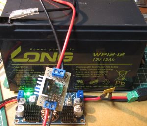
鉛蓄電池なので、定電圧定電流充電ということで、AliExpressでDC入力のCVCC電源ボード(しかも、Stepup-Stepdown両方で動けるもの)が安く出ていたものを購入。ボードの説明をよく見ると、出力側からの電圧印加はダメと書いてあったので、出力側で対策をすることにしました。単純にダイオードを入れようかとも思ったのですが、3Aくらいで充電すると2W近い熱がでることと、以前秋月で見かけたPowerPathコントローラICが気になっていたので、これを買って理想ダイオードの構成としてみました。

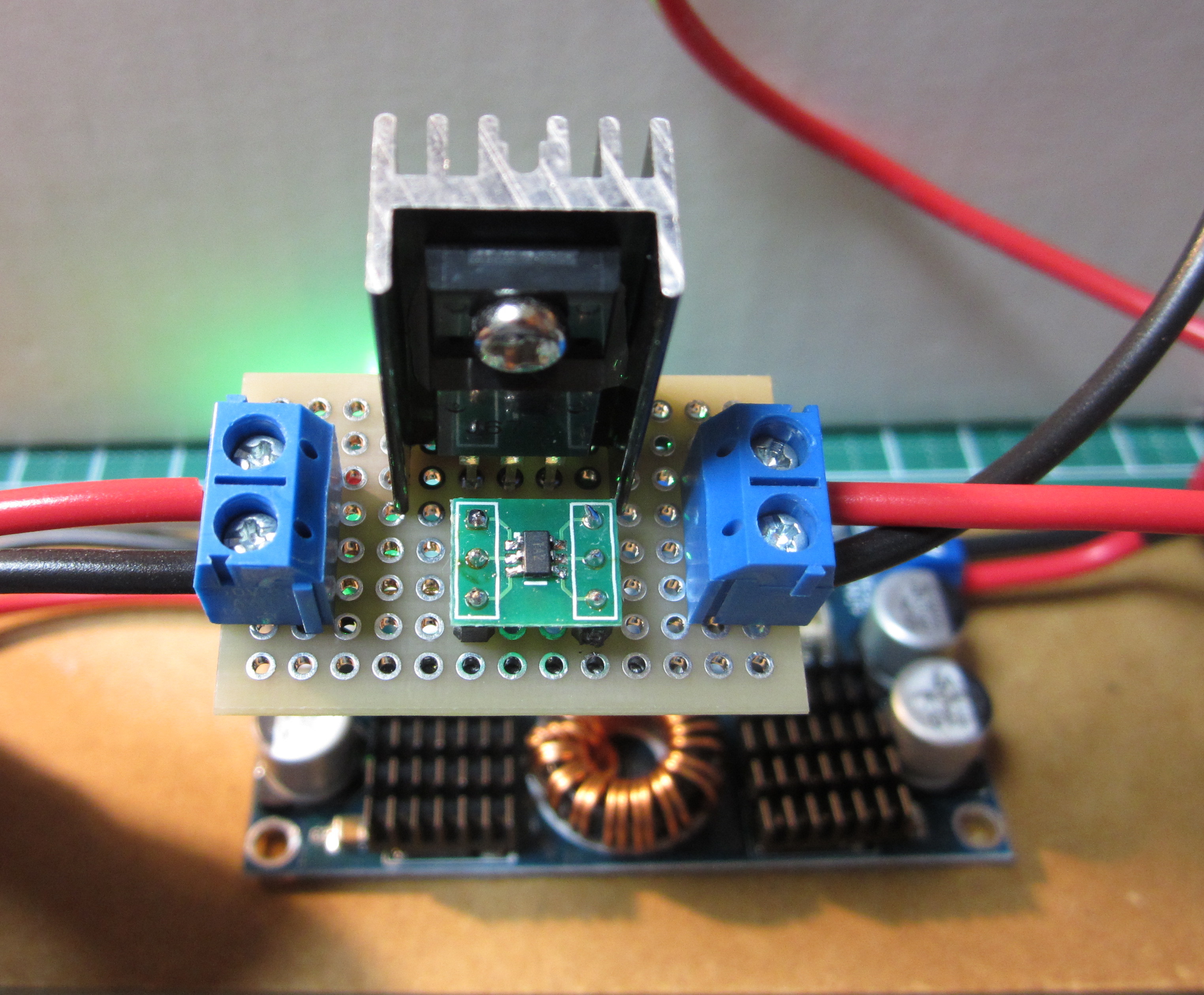
回路はほぼLTC4412のデータシートの表紙の標準的応用例のままですが、あくまで充電器なので、左のバッテリーのマークのところにCVCC電源ボード、右側のLOADのところに鉛蓄電池を接続、WALL ADAPTER INPUTのパスは削除しています。なので、LTC4412とPchのPowerMOSFET(今回は60V36Aの2SJ673を使用)とパスコン、接続部品・ヒートシンクのみというシンプル構成です。

実際に充電している歳の様子です。

今回作った理想ダイオードの部分です。かなり余裕のあるFETを使っているので、もっと大きな電流を流す用途にも使えるはずです。

組み立てが終わったら、まず入力にDC12VのACアダプタを接続してDCDCコンバータ単体で電源投入。UV-SET(入力電圧低下時のカットオフ電圧)FAULTのLEDが点灯しない位置にセットします。出力電圧をモニタしながらVOUT-SETの半固定抵抗を13.8Vにセット。CC-SETの半固定抵抗は(確か)左へ一杯に回しておきます。
次に、理想ダイオード部分をつないで電源投入。出力電圧が13.8Vのままなのを確認します。
さらに、鉛蓄電池のGND側のみ接続、+側はテスタで電流を測定できるようにして一瞬つないで電流を読みます。値は30mAくらいでしたので、CC-SETの半固定抵抗を回して1Aになるところにセットしました。
+側も直結したあと、最後にACアダプタの電源を切った時に、理想ダイオードの出力側は電池の電圧のまま、入力側の電圧は徐々に下がっていくのを確認して、完成です。

今回は補充電として使っていますが、鉛蓄電池ごとケースに入れてもっと充電電流を増やしてやれば、車で移動中に充電しておいてエンジンOFFの電源として使えるかなーとか思っています。(データシートによると3.6Aまでは充電電流を増やせそうです)

ESP32-CAMをテスト

Aliexpressで見つけた格安カメラモジュールのESP32-CAMを入手したので試してみました。OV2640カメラモジュール付きで$7.5という激安っぷりです。

1.ESP-IDFのインストール

まずはファームウェアをビルドするために ESP-IDF をインストールします。
インストールは https://github.com/espressif/esp-idf に沿って行えば難しくありません。(初期のESP8266の頃に比べると随分簡単になったような気がします)

$ sudo apt-get install gcc git wget make libncurses-dev flex bison gperf python python-serial
$ cd ~
$ mkdir -p ~/esp
$ cd ~/esp
$ tar -xzf ~/Downloads/xtensa-esp32-elf-linux64-1.22.0-80-g6c4433a-5.2.0.tar.gz

環境変数を設定するため、~/.profile に以下を書き足します。

export PATH="$PATH:$HOME/esp/xtensa-esp32-elf/bin"
export IDF_PATH=~/esp/esp-idf

書き足したら、一旦ログアウトしてログインし直して、作業環境に反映させます。

2.ハードウェアの準備

ハードウェアの情報については、githubに上がっている仕様書を参考にしました。(※ダウンロードできなくなると手も足も出なくなるので同じものを113990580 ESP32-CAM Product Specificationに上げておきます。)

今回は、USBシリアル変換にFT234X使用のこちらを使いました。Linuxだといろいろトラブルが起きるのですが、セルフパワーで動かす分には大丈夫そうなので使ってみます。

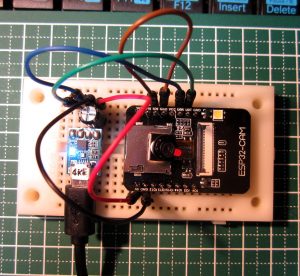
ブレッドボード上にこんな感じで組んでみました。
シリアルの接続と、電源の供給(電源は仕様書の記載ではVccではなく5V端子に供給するようです)、それからブートローダモードにするためのIO0端子をGNDに落とす線の5本です。

3.サンプルのビルド

サンプルをビルドしてみます。

$ cd ~/esp
$ git clone -b v3.1.3 --recursive https://github.com/espressif/esp-idf.git
$ cp -r $IDF_PATH/examples/get-started/hello_world .
$ cd ~/esp/hello_world
$ make menuconfig

で環境設定をします。環境設定が完了したら、IO0端子をGNDに落とした状態でリセットボタンを押してブートローダモードに入ります。
※ウラ面なので、ブレッドボードに設置した状態だと大変です。リセットを押した瞬間に白色LEDが一瞬つくので、リセットを押せたかどうかは確認できます。

このとき、

$ screen /dev/ttyUSB0 115200

としてシリアルをモニタしておくと、以下の表示が出ますのでダウンロード待機状態であることが確認できます。

ets Jun 8 2016 00:22:57

rst:0x1 (POWERON_RESET),boot:0x3 (DOWNLOAD_BOOT(UART0/UART1/SDIO_REI_REO_V2))

waiting for download

screen コマンドを終了してから、

$ make flash

でビルドと書き込みを行います。完了したら、IO0のプルダウンを外してリセットするとシリアルに115200bps N81で以下のように繰り返し出力されます。

ets Jun 8 2016 00:22:57

rst:0xc (SW_CPU_RESET),boot:0x13 (SPI_FAST_FLASH_BOOT)
configsip: 0, SPIWP:0xee
clk_drv:0x00,q_drv:0x00,d_drv:0x00,cs0_drv:0x00,hd_drv:0x00,wp_drv:0x00
mode:DIO, clock div:2
load:0x3fff0018,len:4
load:0x3fff001c,len:5816
load:0x40078000,len:9188
load:0x40080000,len:6084
entry 0x4008032c
I (29) boot: ESP-IDF v3.1.3 2nd stage bootloader
I (29) boot: compile time 02:11:40
I (29) boot: Enabling RNG early entropy source...
I (34) boot: SPI Speed : 40MHz
I (38) boot: SPI Mode : DIO
I (42) boot: SPI Flash Size : 4MB
I (46) boot: Partition Table:
I (49) boot: ## Label Usage Type ST Offset Length
I (57) boot: 0 nvs WiFi data 01 02 00009000 00006000
I (64) boot: 1 phy_init RF data 01 01 0000f000 00001000
I (72) boot: 2 factory factory app 00 00 00010000 00100000
I (79) boot: End of partition table
I (83) esp_image: segment 0: paddr=0x00010020 vaddr=0x3f400020 size=0x071cc ( 29132) map
I (102) esp_image: segment 1: paddr=0x000171f4 vaddr=0x3ffb0000 size=0x022ac ( 8876) load
I (106) esp_image: segment 2: paddr=0x000194a8 vaddr=0x40080000 size=0x00400 ( 1024) load
I (110) esp_image: segment 3: paddr=0x000198b0 vaddr=0x40080400 size=0x06760 ( 26464) load
I (130) esp_image: segment 4: paddr=0x00020018 vaddr=0x400d0018 size=0x11150 ( 69968) map
I (155) esp_image: segment 5: paddr=0x00031170 vaddr=0x40086b60 size=0x02188 ( 8584) load
I (164) boot: Loaded app from partition at offset 0x10000
I (164) boot: Disabling RNG early entropy source...
I (166) cpu_start: Pro cpu up.
I (170) cpu_start: Starting app cpu, entry point is 0x40080ea0
I (162) cpu_start: App cpu up.
I (181) heap_init: Initializing. RAM available for dynamic allocation:
I (187) heap_init: At 3FFAE6E0 len 00001920 (6 KiB): DRAM
I (193) heap_init: At 3FFB3300 len 0002CD00 (179 KiB): DRAM
I (200) heap_init: At 3FFE0440 len 00003BC0 (14 KiB): D/IRAM
I (206) heap_init: At 3FFE4350 len 0001BCB0 (111 KiB): D/IRAM
I (212) heap_init: At 40088CE8 len 00017318 (92 KiB): IRAM
I (219) cpu_start: Pro cpu start user code
I (237) cpu_start: Starting scheduler on PRO CPU.
I (0) cpu_start: Starting scheduler on APP CPU.
Hello world!
This is ESP32 chip with 2 CPU cores, WiFi/BT/BLE, silicon revision 1, 4MB external flash
Restarting in 10 seconds...
Restarting in 9 seconds...
Restarting in 8 seconds...
Restarting in 7 seconds...
Restarting in 6 seconds...
Restarting in 5 seconds...
Restarting in 4 seconds...
Restarting in 3 seconds...
Restarting in 2 seconds...
Restarting in 1 seconds...
Restarting in 0 seconds...
Restarting now.

ということで、Hello world!を出力後、再起動を繰り返します。

4.カメラにブラウザでアクセス

以下のサイトを参考にして行いました。(参考というか、Windows環境かLinux環境かの違い程度で概ねそのまんまですが)
https://robotzero.one/esp32-camera-module/

顔認識のサンプルをgitから引っ張ってきます。

$ cd /esp
$ git clone --recursive https://github.com/espressif/esp-who.git

この中のCamera Web Server Exampleを動かしてみます

$ cd ~/esp/esp-who/examples/single_chip/camera_web_server/
$ make menuconfig

以下の項目を設定して保存します。

Serial flasher config —> Default serial port (Change to the port number shown in Device Manager – ie COM3)
Camera Web Server —> WiFi Settings —> (Add your WiFi SSID and Password)
Camera Web Server —> Camera Pins —> Select Camera Pinout —> (Select ESP32-CAM by AI-Thinker)
Component config —> ESP32-specific —> SPI RAM config —> Type of SPI RAM chip (Auto-detect)

保存したら、ビルド&書き込みです。

$ cd ~/esp/esp-who/examples/single_chip/camera_web_server/
$ make flash

しかし、ここで

CC build/main/app_httpd.o
~/esp/esp-who/examples/single_chip/camera_web_server/main/app_httpd.c:15:29: fatal error: esp_http_server.h: No such file or directory
compilation terminated.
~/esp/esp-idf/make/component_wrapper.mk:285: recipe for target 'app_httpd.o' failed
make[1]: *** [app_httpd.o] Error 1
~/esp/esp-idf/make/project.mk:468: recipe for target 'component-main-build' failed
make: *** [component-main-build] Error 2

というエラーが発生してしまいました。
ぐぐると、esp-idfが古そうな感じです。しかし、

$ cd $IDF_PATH
$ pwd
~/esp/esp-idf
$ git fetch
$ git checkout v3.1.3
HEAD is now at cf5dbadf4 Merge branch 'bugfix/backtrace_from_interrupts_backport_v3.1' into 'release/v3.1'
$ git submodule update --init --recursive

としても更新してもダメでした。でも、よくみるとesp-whoディレクトリの下に、esp-idfが丸ごと含まれているっぽいです。ですので、こちらを IDF_PATH に設定して試してみます。

$ pwd
~/esp/esp-idf
$ export IDF_PATH=~/esp/esp-who/esp-idf
$ cd ~/esp/esp-who/examples/single_chip/camera_web_server/
$ make flash
  :
  :
cryptography
Please refer to the Get Started section of the ESP-IDF Programming Guide for setting up the required packages. Alternatively, you can run "/usr/bin/python -m pip install --user -r ~/esp/esp-who/esp-idf/requirements.txt" for resolving the issue.
~/esp/esp-who/esp-idf/make/project.mk:454: recipe for target 'check_python_dependencies' failed
make: *** [check_python_dependencies] Error 1

ということで、python絡みで何か文句を言っています。結局は pip がないために依存関係が満たせていないようです。

$ cd ~/esp/esp-who/
$ curl https://bootstrap.pypa.io/get-pip.py -o get-pip.py
% Total % Received % Xferd Average Speed Time Time Time Current
Dload Upload Total Spent Left Speed
100 1659k 100 1659k 0 0 8598k 0 --:--:-- --:--:-- --:--:-- 8554k
$ sudo python get-pip.py
$ /usr/bin/python -m pip install --user -r ~/esp/esp-who/esp-idf/requirements.txt

としてpipと必要なものをインストールした後、

$ cd ~/esp/esp-who/examples/single_chip/camera_web_server/
$ make flash

で無事にビルド&書き込みができました。

しかし、書き込んでIO0のプルダウンを外してリセットしてもSSIDが見えません。

$ screen /dev/ttyUSB0 115200

で見てみると、

  :
  :
I (307) wifi: Init static rx buffer size: 1600
I (317) wifi: Init static rx buffer num: 10
I (317) wifi: Init dynamic rx buffer num: 32
I (367) camera wifi: wifi_init_softap finished.SSID:ESP32-Camera password:
�
Bwownout detector was triggere�

ets Jun 8 2016 00:22:57

rst:0xc (SW_CPU_RESET),boot:0x13 (SPI_FAST_FLASH_BOOT)
configsip: 0, SPIWP:0xee
clk_drv:0x00,q_drv:0x00,d_drv:0x00,cs0_drv:0x00,hd_drv:0x00,wp_drv:0x00
mode:DIO, clock div:1
load:0x3fff0018,len:4
load:0x3fff001c,len:6668
load:0x40078000,len:10976
  :
  :

ということで、Wi-Fiの初期化のところでBrownout Detectでリブートを繰り返しています。

PCから長いUSBケーブルで給電とシリアルコンソール確認を兼ねているので、電源のインピーダンスが高いことは確かです。そこで、1000uFのコンデンサをVcc-GND間に追加したところ、Webサーバの起動まで進むようになりましたが、スマートフォンを帰属させるとやはりリブートしてしまいます。そこで、短いケーブルでACアダプタから直接給電したところ、192.168.4.1にブラウザでアクセスすると設定画面が表示され、Get stillでカメラ画像も取得できるところまで行きました。
しかし、それでも動作が不安定です。FT234Xのシリアル変換モジュールには100mAのポリスイッチが入っているので、こいつが悪さをしているのか、あるいはまだ電源のインピーダンスが高いのかわかりませんが、今日はここまでとします。今後、レスポンスがどのくらいなのか、確認はしてみたいと思います。

#どのくらいのパフォーマンスか見たいだけなので、もう少し試してみたら、積みボードになりそう。

TTGO T-Cameraを開封レビュー

Twitterで見かけたESP32 WROVERとセンサー色々搭載のTTGO T-Cameraを購入してみました。(⇒Aliexpressのページ

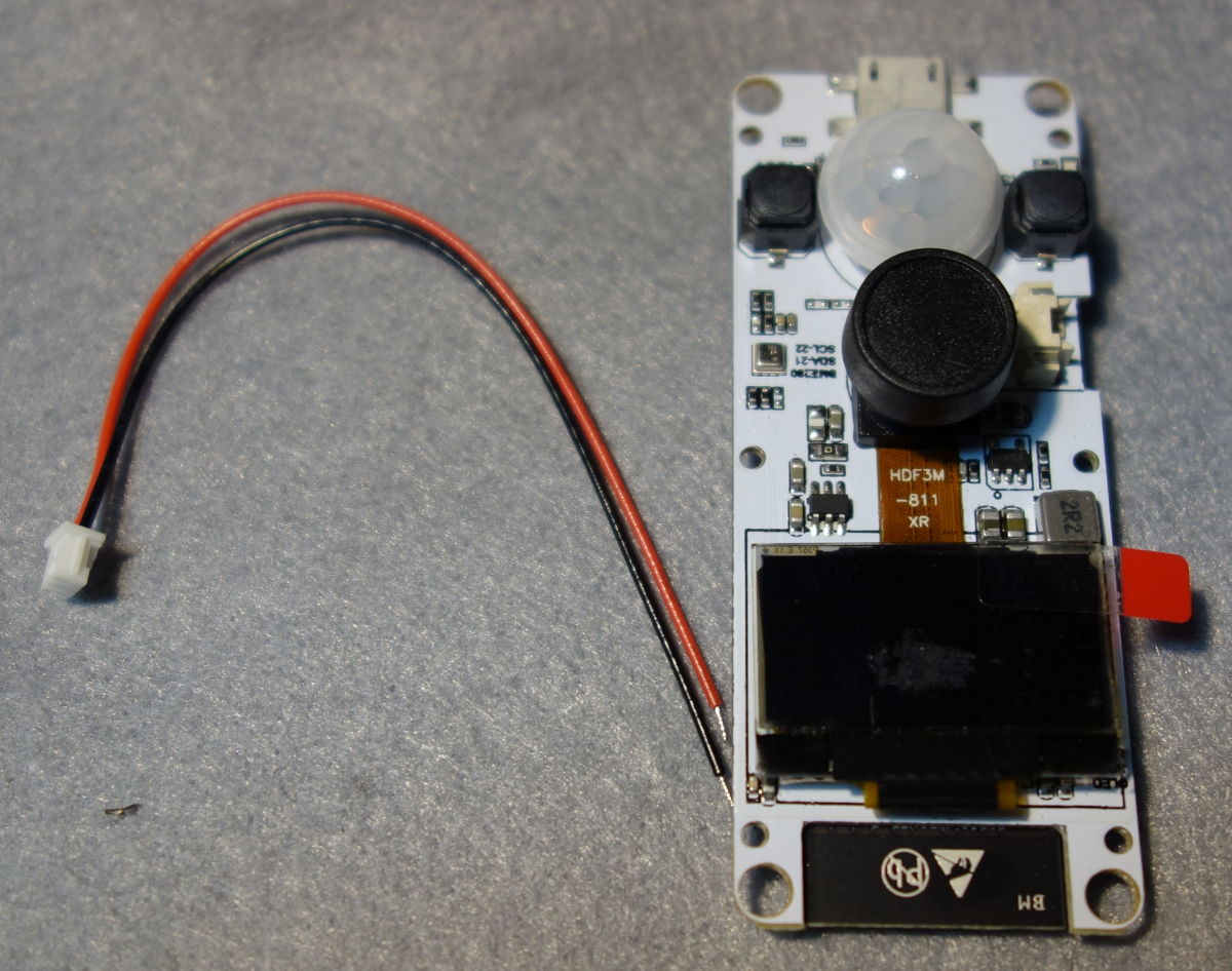
ESP32 WROVERにカメラ、人感センサ、温度・湿度・気圧センサなどのセンサ、0.96インチのOLEDディスプレイ、I2Cでの外部拡張端子がついて、魚眼レンズタイプで17.6ドル(今はさらに下がって16.5ドル)で入手できる上に、githubでArduino環境のソースコードまで手に入ります。

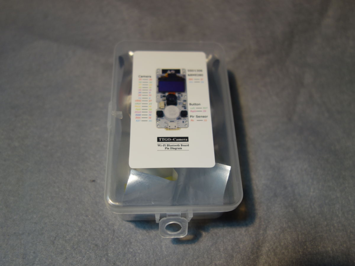
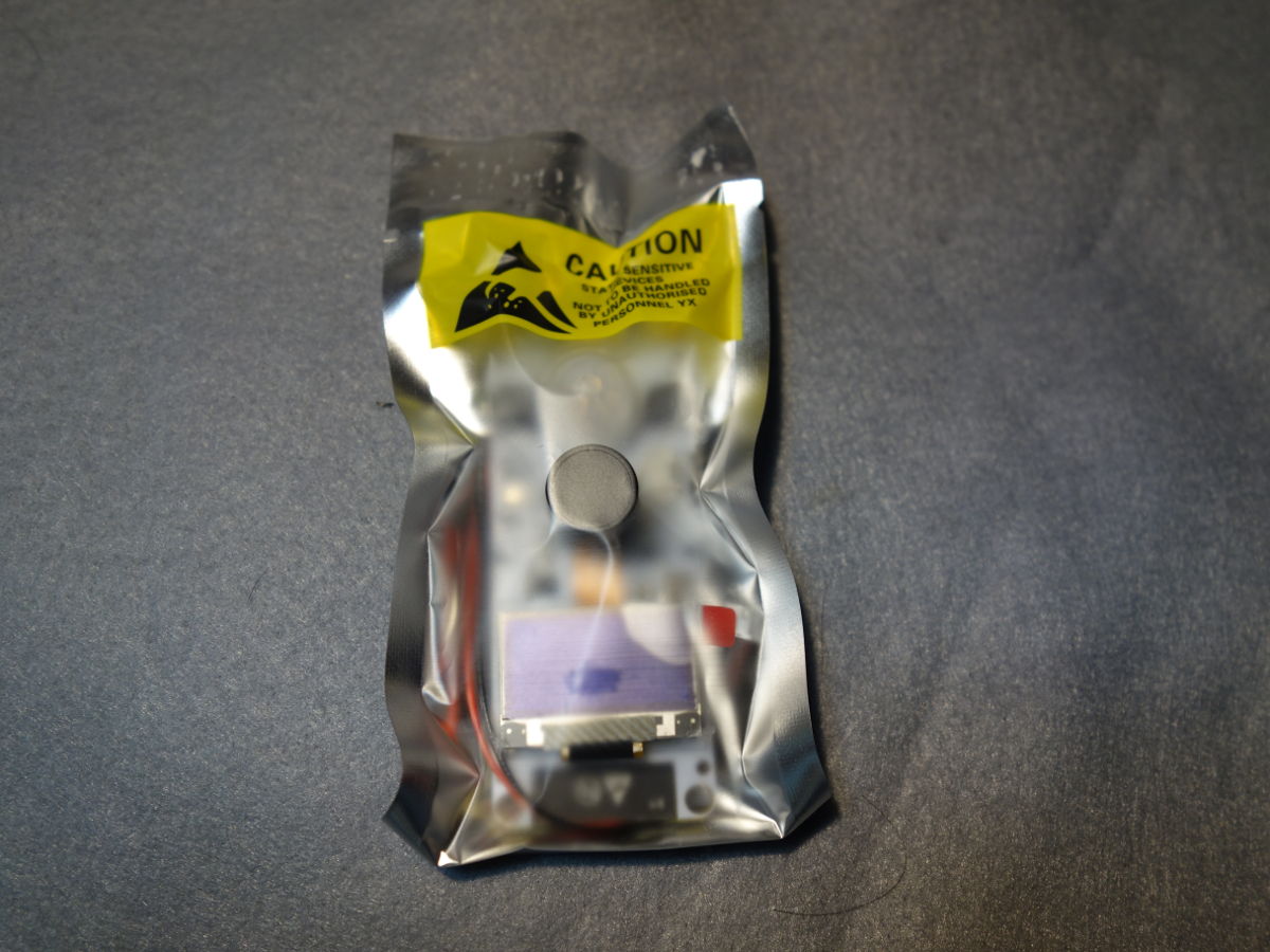
梱包は比較的簡易なものでしたが、このようなポリプロピレン製のケースに入っているので、潰れて送られてくる、ということはなさそうです。

ポリプロピレンケースの中に入っていた製品はこのように帯電防止の袋に入れられて密封されていました。

開封するとこんな感じで、電池を接続するためのケーブルも添付されていました。ここにLiPoをつないで充電ができるといいのですが、そこまではまだ調べていません。

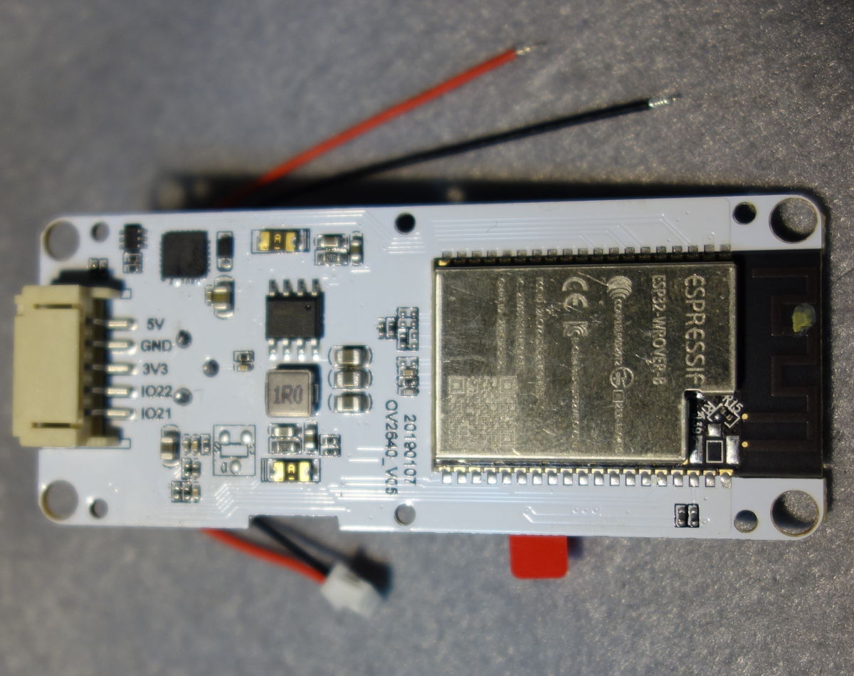
裏面はこんな感じです。

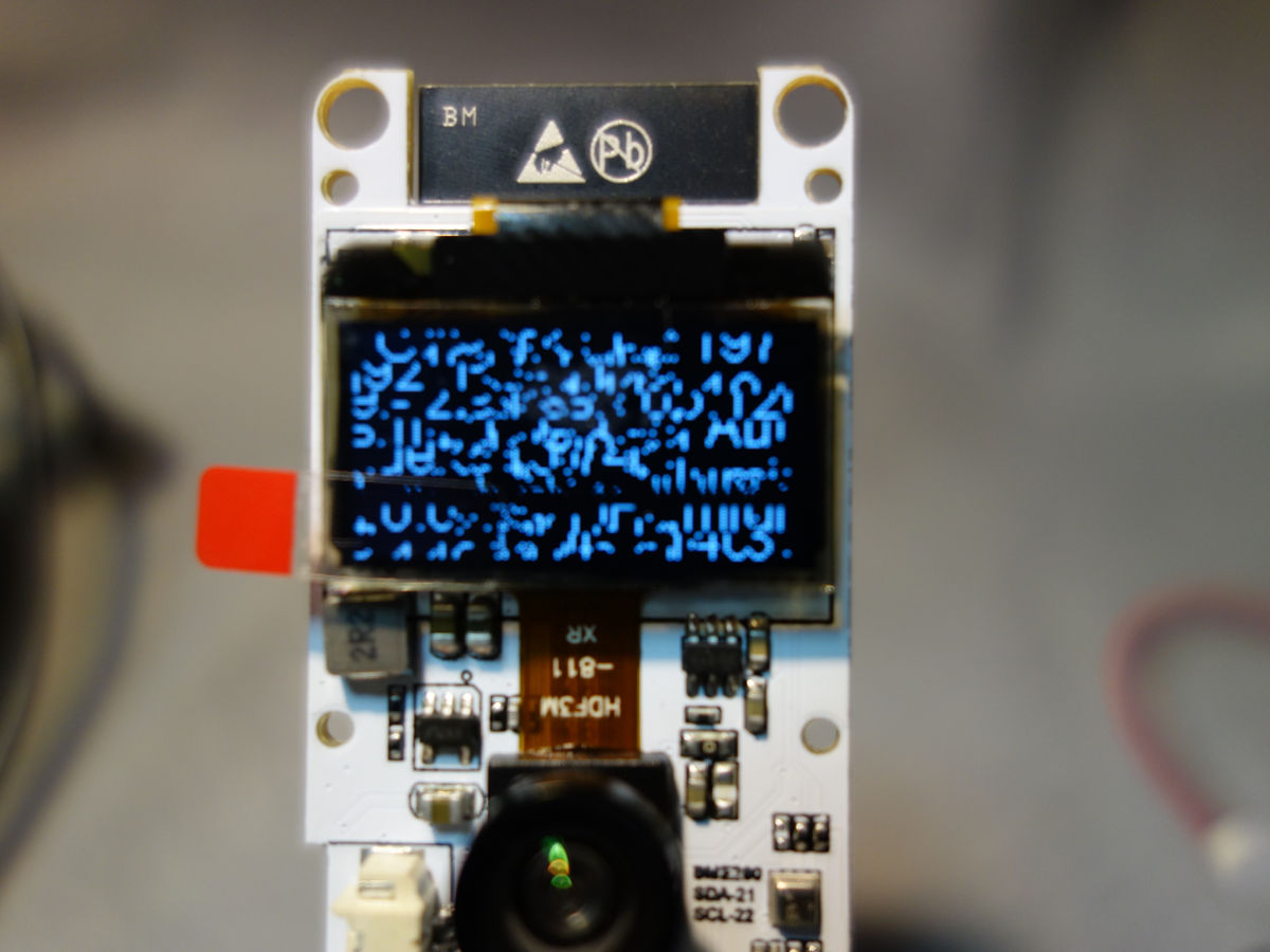
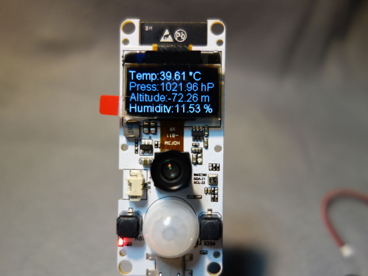
MicroUSBの端子がついているので早速適当なUSBの電源アダプタにつないでみると、こんな画面で崩れて表示されてしまいました。

この状態でも無線APとして動作していて、スマートフォンで接続でき、ブラウザで 2.2.2.1 に接続するとカメラ画像の取得などができました。

電源をPCから取ると、このように正常に表示されました。ACアダプタやモバイルバッテリーは軽負荷時にノイズが大きいので、その影響だったのだと思います。
しかし、温度表示が39.61℃と異常な値が表示されています。カメラ右下についているのがBME280だと思いますが、ESP32の自己発熱でかなり温度が上がってしまうのでしょうか??
温度がおかしいと、気圧や湿度も補正できないはずなので、残念です。

・・・と思ったら、バージョンアップ(?)により役に立たないBME280は削除されているようです。

ま、とりあえずおもちゃ入手レポートでした。(なんかおもちゃばっかりですが・・)

追伸

IPS液晶搭載の後継モデルが出ていました。人感センサとスイッチがなくなっているようですが、カラー液晶、MicroSDカードスロット搭載、BME280復活となっています。スイッチが残っていればUIとかも付けられるかな?と思うのですが、スイッチ無しなので用途がいまいち思いつかないところです。(バッテリー駆動するなら不要なときは液晶をOFFにしたいですし)

静的サイトジェネレータHugoを試してみた

このサイトは編集をいつでもどこでも簡単にできるようにWordPressで作成していますが、内容を固定したサイトの場合には、WordPressで作成すると定期的にアップデートが必要となるので結構管理が面倒です。(それでも、WordPressはセキュリティアップデートは勝手にやってくれるので、だいぶ楽ですが)

また、プラグインやテーマもちょっとマイナーなものを入れると、本体のアップデートについていけず、結構悩むことになります。

で、最近知ったのが静的サイトジェネレータというもので、マークダウン言語で書いた記事をHTMLとCSSに変換してくれるものだそうです。HTMLとCSSだけでデータベースなどはないのでセキュリティ上の心配も少なくて済むようです。で、変換したHTMLとCSSをまるごとサーバ上にアップロードすればOK(実際には同期するのかもしれませんが)ということらしいです。

今回はその静的サイトジェネレータの中からHugoというのを試してみることにしました。

1.Hugoの環境構築

今回は諸般の事情から、素のUbuntu18.04LTS環境に導入してみます。Hugoで検索すると、WindowsかMacOSのものが大部分で、Linux環境の場合にはどういうわけか(探し方が悪いのか)古いものしか見つかりません。どうせなら最新版をインストールしたいところです。そこで参考にしたのは一つ目はこちらの記事です。何はともあれ、参考にしながら最新版をgithubからダウンロードしてインストールしてみます。

下記手順で素のUbuntu18.04LTSに対してアップデートとVirtualBoxのGuest Addtionsのインストールを行った後、Hugoのバイナリパッケージをインストールします。
※今後の再テストを短時間で行うため、VirtualBoxのディスクイメージのスナップショットも採取しています。

$ sudo apt update
$ sudo apt upgrade
(一旦再起動)
$ sudo apt install build-essential perl make gcc git
(VirtualBoxのGuest Additionsをインストールして一旦シャットダウン、スナップショットを取って再起動)
$ wget https://github.com/gohugoio/hugo/releases/download/v0.54.0/hugo_0.54.0_Linux-64bit.deb
$ sudo apt install ./hugo_0.54.0_Linux-64bit.deb
$ hugo version

2.新しいサイトの作成

$ mkdir WebSite
$ cd WebSite
$ hugo new site hugo.example.com

3.新しいページの作成

以下の方法で新しいページを作成します。

$ hugo new <SECTIONNAME>/<FILENAME>.<FORMAT>

実際にやってみます。

$ cd hugo.example.com
$ ls
$ hugo new post/test-page.md

として、contentディレクトリの下のpostディレクトリの下に記事を生成します。生成したら、自動生成されたファイルcontent/post/test-page.md を編集します。冒頭の draft: の行は削除します。(この行があると、記事が生成されません)

---
title: "Test Page"
date: 2019-03-05T01:02:03Z
---

# Hello World

This is my first hugo site, wooo!!

```
hugo_install="success"
if [[ $hugo_install == "success" ]]; then
  echo "Happy me"
```

bye!

4.テーマをダウンロード

テーマをダウンロードします。ここでは試しに mainroad というのを使ってみます。

$ cd theme
$ git clone https://github.com/vimux/mainroad
$ cd ..

mainroadというテーマを使うために、config.toml に

theme = "mainroad"

を書き足します。

5.サイトを生成してみる

$ hugo

で、publicというディレクトリが生成されて中にデータが生成されます。

$ hugo server

で組み込みサーバーが起動するようです。http://localhost:1313/ でインデックスページにアクセスできますが、かなり質素です(mainroadというテーマはこんなに質素じゃないはずなので要調査)。Ctrl+C で停止できます。

このまま、

$ cd hugo.example.com
$ hugo new post/sample.md

として、もう1ページを作成、content/post/sample.md を編集します。冒頭の draft: の行は削除しつつ適当に内容を作成すると、自動的にブラウザで開いていた記事のリストが更新されます。

記事を一通り作成したら、publicディレクトリを丸ごとWebサーバにアップロードすることで、公開完了、ということみたいです。(実際には rsync などで同期を取る形で運用するのが楽なのだと思います)

6.参考になりそうなもの

ラジアスゲージ作ってみた

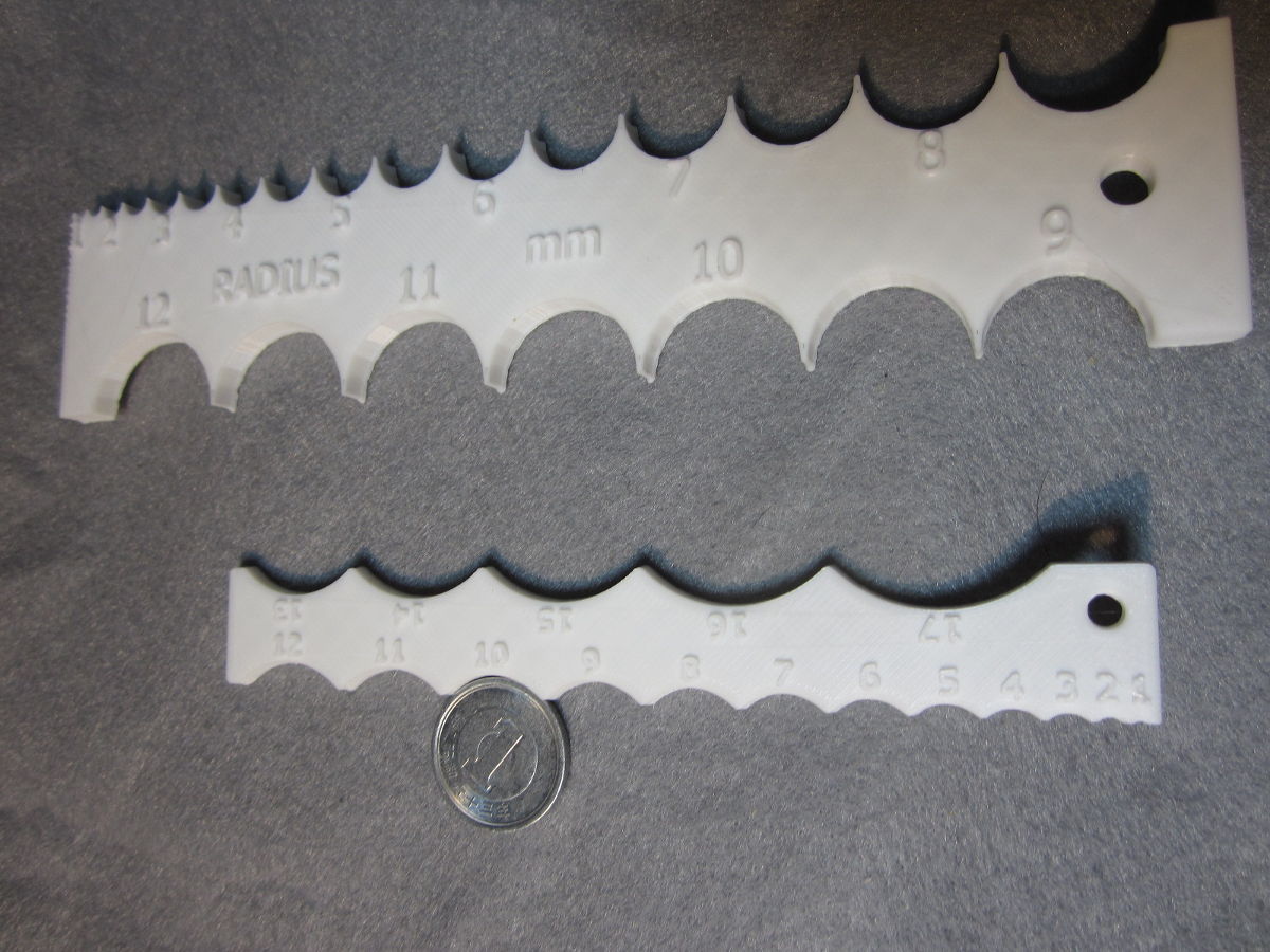
これまでFusion360で現物合わせで何か作る場合には、円弧の部分は目分量でデザインして、現物合わせしていました。・・・がラジアスゲージ作ってみました。

上は Thingiverseにあったものを出力しただけのものですが、180度で作成されているため、例えばスマートフォンの角のRがいくつになっているのか等は確認できません。なので、下にあるように90度で設計してみました。

写真は厚さ3mmで出力したのですが、もう少し厚みがあってもいいかと思って5mmで出力し直しています(Fusion360の画面キャプチャは5mmに変更後です)

3Dプリンタで出力する際には少し潰れ気味(つまり、実際の半径は少し小さくなる方向)になるので、精度があるものではありませんが目安としては十分です。手軽にこういうものを作って使えるのはやっぱり便利です。

MKRVIDOR4000_graphicsの中身を見てみる

Quartus Prime LiteでMKRVIDOR4000_graphicsの中身を見てみます。

projectディレクトリの中にMKRVIDOR4000_graphics_lite.qpfがあるので、これをQuartus Prime Liteで開いてみます。

左の方のProject Navigatorのところでソースツリーっぽいところ(Entity)が見えて、ここに MKRVIDOR4000_graphics_top があるので、これをクリックすると、そのソースコードが開きました。トップレベルモジュールの verilog ソースコードのようです。端子の定義と信号の定義、出力バッファ近傍のセレクタなどがあるようです。

Project NavigatorでIP Componentsを選択し、EntityのところでMKRVIDOR4000_graphics_lite_sysをダブルクリックすると、Platform Designerが開いてIPマクロ間の接続の全体像が少しわかります。nios CPUのメモリマップもここで確認することができて、niosの命令バスはオンチップメモリとQSPIフラッシュメモリからフェッチできるようになっているようです。(SDRAM ARBITERとsdramのところを編集するとSDRAMからのアクセスもできるように修正できるっぽい雰囲気です)

上の方の再生ボタンみたいな Start Compilation をクリックすると論理合成して、配置配線、タイミング解析をしてくれます。Task のパネルに進捗が表示されて、完了すると、Entityのところに各モジュールの構造がツリー状に表示されました。このあたりをもう少し見ていくといろいろわかりそうです。

一方で、VidorBitstream-releaseディレクトリの下にipというディレクトリがあり、ここにIPコアのコードが入っているようです。各モジュールの softcore というディレクトリの下にFPGA側のniosのコードが入っています。graphicsの描画処理は ip/GFX/softcore/src/gfx.c というソースの中の gfxRpc() の中で受け取ったリモートプロシージャコールのパラメータに応じて描画関数を呼び出していました。

また、VidorBitstream-release/project/MKDVIDOR4000_graphics/build/software/launcher_lite_bspの下にsummary.html というファイルがあり、これがnios側の諸情報のようです。この中にLinkerのSectionに関する情報があり、nios側のコードもデータもbssもheapもオンチップメモリ上に配置されているようです。また、mem_init.mk というファイルによるとリセットベクターも 0x00a00000 となっているようで、これはメモリマップによればやはりオンチップメモリのようです。nios上のコードはniosとは関係なくオンチップメモリ上に転送しているのかもしれません。(FPGAのコンフィギュレーション時に書き込まれるんでしょうかね??)

まだまだ弄るといろいろわかりそうですが、時間もかかりそうです。

VidorBitstreamがビルドできるようになりました

MKRVIDOR4000_graphicsのサンプルスケッチが中途半端に表示がされる原因についてもわかりました。

中途半端に表示がされるのは、サンプルスケッチ VidorDrawLogo の冒頭にある

vdgfx.fillRect(0,0,640,480,vdgfx.White());

のFPGA側での処理が遅いことと、初期化時にそもそも白で全面クリアされていること、ARM側の処理でFPGA側の処理完了を待っていてもタイムアウトするほど遅いことが原因です。初期化時にそもそも白で全面クリアされているので、その上に処理の遅いfillRect()が同色で描画されても、画面上は何も見えません。fillRect()の処理が終わった後に描画要求が飛んでくる部分だけが見える、というわけです。

その証拠に、

vdgfx.fillRect(0,0,640,480,vdgfx.Blue());

と色を変えてやると、ちょっとずつ青く塗っていく処理と、その後で一部の文字が描画されるのがわかります。

というわけで、fillRect()の部分をコメントアウトすることで無事に表示されるようになりました。

まとめ

Linux Mint 19.1 上の Quartus Prime Lite Edition 18.1で MKR Vidor 4000 のFPGAのコードをビルドする場合は以下の点に注意。

  1. apply_quartus_patches.shでパッチを当てる際には、arduino_generic_quad_spi_controller2_sw.tcl に対するパッチ適用は失敗するので、手動で適用すべし。
  2. スケッチサンプルの冒頭のfillRect()はコメントアウトすべし(もしくは、色を変えた上で、Arduinoライブラリの中の VidorMailbox.cpp の冒頭のMB_TIMEOUTを大きく伸ばすべし)

おまけ

Arduino側(ARM側)のライブラリを見ていてARM側からは以下のようにFPGA側にリクエストが伝わるようです。

Vidor_GFX.cpp ⇒ VidorMailbox.cpp ⇒ VidorJTAG.cpp ⇒ jtag_host.cpp ⇒ JTAG信号線

グラフックスの関数はリモートプロシージャコール(rpc)のパラメータの配列(uint32_tの配列)に変換されて、VidorMailbox.sendCommand() が呼び出されます。パラメータはVidorJTAG.writeBuffer()の引数として渡されますが、最終的には jtag_host.cpp で1ビットずつJTAG信号としてFPGA側へ転送されます。すべてソフトウェアでJTAG信号を生成しているようなので、コマンドの転送自体が遅そうです。Mailboxへのコマンド送信後の応答待ち時間は VidorMailbox.cpp の冒頭の MB_TIMEOUT で定義されていて、5000ms=5秒になっているようです。
FPGA側の処理については調べていないのでこれからです。

VidorBitstreamがビルドできない原因を探ってみました

気を取り直して、MKRVIDOR4000_graphicsがビルドできない原因を考えてみます。

まずは改めてビルドして気になるところを洗い出してみます。

$ ./intelFPGA_lite/18.1/nios2eds/nios2_command_shell.sh 
------------------------------------------------
Altera Nios2 Command Shell [GCC 4]

Version 18.1, Build 625
------------------------------------------------
$ cd intelFPGA_lite/VidorBitstream-release/projects/MKRVIDOR4000_graphics/
$ time build_all.sh
2019.02.24.15:35:06 Info: Saving generation log to /home/xxx/intelFPGA_lite/VidorBitstream-release/projects/MKRVIDOR4000_graphics/build/MKRVIDOR4000_graphics_lite_sys/MKRVIDOR4000_graphics_lite_sys_generation.rpt
2019.02.24.15:35:06 Info: Starting: <b>Create HDL design files for synthesis</b>
2019.02.24.15:35:06 Info: qsys-generate /home/xxx/intelFPGA_lite/VidorBitstream-release/projects/MKRVIDOR4000_graphics/build/MKRVIDOR4000_graphics_lite_sys.qsys --synthesis=VERILOG --output-directory=/home/xxx/intelFPGA_lite/VidorBitstream-release/projects/MKRVIDOR4000_graphics/build/MKRVIDOR4000_graphics_lite_sys/synthesis --family="Cyclone 10 LP" --part=10CL016YU256C8G
2019.02.24.15:35:06 Info: Loading build/MKRVIDOR4000_graphics_lite_sys.qsys
  :
  :
##########################################
#        using local bsp settings        #
##########################################
nios2-bsp: Using /home/xxx/intelFPGA_lite/18.1/nios2eds/sdk2/bin/bsp-set-defaults.tcl to set system-dependent settings.
nios2-bsp: Updating existing BSP because ./build/software/launcher_lite_bsp/settings.bsp exists.
nios2-bsp: Running "nios2-bsp-update-settings --settings ./build/software/launcher_lite_bsp/settings.bsp --bsp-dir ./build/software/
  :
  :
INFO: Updating BSP settings...
INFO: nios2-bsp-update-settings --settings ./build/software/launcher_lite_bsp/settings.bsp --bsp-dir ./build/software/launcher_lite_bsp --sopc ./build/MKRVIDOR4000_graphics_lite_sys.sopcinfo --script /home/xxx/intelFPGA_lite/18.1/nios2eds/sdk2/bin/bsp-set-defaults.tcl 
  :
  :
INFO: Initializing BSP components...
  :
  :
INFO: Finished initializing SOPC project local software IP. Total time taken = 2 seconds
INFO: Searching for BSP components with category: driver_element
INFO: Searching for BSP components with category: software_package_element
INFO: No memory regions found in BSP Settings File. Default memory regions generated. 
INFO: Found Flash Memory: qspi_avl_mem for CPU: nios2_gen2_0
INFO: Loading drivers from ensemble report. 
INFO: Finished loading drivers from ensemble report.
INFO: Tcl message: "No STDIO character device"
INFO: Tcl message: "System timer device is timer_0"
INFO: Tcl message: "Default instruction linker sections mapped to onchip_memory2_0"
INFO: Tcl message: "Default data linker sections mapped to SDRAM_ARBITER"
INFO: Tcl message: "Setting specified section .rwdata to map to region onchip_memory2_0"
INFO: Tcl message: "Setting specified section .bss to map to region onchip_memory2_0"
INFO: Tcl message: "Setting specified section .heap to map to region onchip_memory2_0"
INFO: Tcl message: "Setting specified section .entry to map to region onchip_memory2_0"
INFO: Tcl message: "Setting specified section .text to map to region onchip_memory2_0"
INFO: Tcl message: "Setting specified section .rodata to map to region onchip_memory2_0"
INFO: Tcl message: "Setting specified section .data to map to region onchip_memory2_0"
INFO: Tcl message: "Setting specified section .stack to map to region onchip_memory2_0"
INFO: Tcl message: "No bootloader located at the reset address."
INFO: Tcl message: "Application ELF allowed to contain code at the reset address."
INFO: Tcl message: "The alt_load() facility is enabled."
INFO: Tcl message: "The .rwdata section is copied into RAM by alt_load()."
SEVERE: Driver not found: 'arduino_generic_quad_spi_controller2 of any version
WARNING: Tcl command "set_driver arduino_generic_quad_spi_controller2 qspi" error: Driver not found: 'arduino_generic_quad_spi_controller2 of any version
  :
  :
Compiling sf.c...
nios2-elf-gcc -xc -MP -MMD -c  -I./HAL/inc -I. -I./drivers/inc -pipe -D__hal__ -DALT_NO_C_PLUS_PLUS -DALT_NO_CLEAN_EXIT -D'exit(a)=_exit(a)' -DALT_NO_EXIT -DALT_USE_DIRECT_DRIVERS -DALT_NO_INSTRUCTION_EMULATION -DALT_USE_SMALL_DRIVERS -DSMALL_C_LIB -DALT_SINGLE_THREADED  -DNO_RPC=1  -Os -g -Wall -DFREE_VERSION=1 -mno-hw-div -mno-hw-mul -mno-hw-mulx -mgpopt=global   -o obj/drivers/src/sf.o drivers/src/sf.c
drivers/src/sf.c:31:52: fatal error: arduino_generic_quad_spi_controller2.h: No such file or directory  <---- これが致命的にだめな気がする
compilation terminated.
Makefile:681: recipe for target 'obj/drivers/src/sf.o' failed
make[1]: *** [obj/drivers/src/sf.o] Error 1
Makefile:900: recipe for target '../launcher_lite_bsp-recurs-make-lib' failed
make: *** [../launcher_lite_bsp-recurs-make-lib] Error 2
make: ディレクトリ '/home/xxx/intelFPGA_lite/VidorBitstream-release/projects/MKRVIDOR4000_graphics/build/software/launcher' から出ます
make failed
##########################################
#        using local bsp settings        #
##########################################
  :
  :
2019/02/24 15:41:20 - (情報) elf2flash: args = --input=build/software/MKRVIDOR4000_graphics/MKRVIDOR4000_graphics_lite.elf --output=build/output_files/MKRVIDOR4000_graphics_lite.flash --base=0x008E0000 --end=0x008FFFFF --verbose --save
2019/02/24 15:41:20 - (普通) elf2flash: Starting
2019/02/24 15:41:20 - (普通) elf2flash: Done
projects
ip
cp: -r not specified; omitting directory './ip/GFX/arduino/Vidor_GFX/examples'
cp: -r not specified; omitting directory './ip/QUAD_ENCODER/arduino/VidorEncoder/examples'
cp: -r not specified; omitting directory './ip/NEOPIXEL/arduino/VidorNeopixel/examples'
cp: -r not specified; omitting directory './ip/MIPI_RX_ST/arduino/VidorCamera/examples'

real	6m31.672s
user	10m18.175s
sys	0m15.768s
$

途中で

SEVERE: Driver not found: 'arduino_generic_quad_spi_controller2 of any version
WARNING: Tcl command "set_driver arduino_generic_quad_spi_controller2 qspi" error: Driver not found: 'arduino_generic_quad_spi_controller2 of any version
  :
  :
drivers/src/sf.c:31:52: fatal error: arduino_generic_quad_spi_controller2.h: No such file or directory  <---- これが致命的にだめな気がする
compilation terminated.

というところがあって、arduino_generic_quad_spi_controller2が絡んで致命的にだめな感じです。

~/intelFPGA_lite/18.1/ip/altera/pgm/arduino_generic_qpsi_controller2 の下でリジェクトされたパッチが2つあったのですが、そのうちの対象の一つが arduino_generic_quad_spi_controller2_sw.tcl というファイル名なので、何か関連がありそうです。リジェクトされたパッチ arduino_generic_quad_spi_controller2_sw.tcl.rej を見てみます。

--- pgm/arduino_generic_qspi_controller2/arduino_generic_quad_spi_controller2_sw.tcl	2018.18-22 19:45:29.112314100 +0200
+++ pgm/arduino_generic_qspi_controller2/arduino_generic_quad_spi_controller2_sw.tcl	2018.18-22 19:45:06.047573800 +0200
@@ -16,10 +16,10 @@
 #
 
 # Create a new driver
-create_driver altera_generic_quad_spi_controller2
+create_driver arduino_generic_quad_spi_controller2
 
-# Associate it with some hardware known as "altera_generic_quad_spi_controller2"
-set_sw_property hw_class_name altera_generic_quad_spi_controller2
+# Associate it with some hardware known as "arduino_generic_quad_spi_controller2"
+set_sw_property hw_class_name arduino_generic_quad_spi_controller2
 
 # The version of this driver
 set_sw_property version 18.1
@@ -50,11 +50,11 @@
 #
 
 # Header files
-add_sw_property include_source HAL/inc/altera_generic_quad_spi_controller2.h
-add_sw_property include_source inc/altera_generic_quad_spi_controller2_regs.h
+add_sw_property include_source HAL/inc/arduino_generic_quad_spi_controller2.h
+add_sw_property include_source inc/arduino_generic_quad_spi_controller2_regs.h
 
 # C/C++ source files
-add_sw_property c_source HAL/src/altera_generic_quad_spi_controller2.c
+add_sw_property c_source HAL/src/arduino_generic_quad_spi_controller2.c
 
 # This driver supports HAL & UCOSII BSP (OS) types
 add_sw_property supported_bsp_type HAL

この中に、

 # Create a new driver
-create_driver altera_generic_quad_spi_controller2
+create_driver arduino_generic_quad_spi_controller2

というようなところがあるので、なんか関連はありそうです。arduino_generic_quad_spi_controller2_sw.tcl の中をみても、なぜリジェクトされたのかイマイチよくわかりません(適用されても良さそうな気がする)が、とにかく手動で適用してみます。(追記: 要は、arduino_generic_quad_spi_controller2_sw.tcl というファイルの中の16行目からの10行くらいと、50行目からの11行くらいのところにある「altera_generic_quad_spi_controller2」を「arduino_generic_quad_spi_controller2」に書き換える、ということです。)

もう一つのarduino_generic_qspi_controller2_hw.tclに対して1箇所失敗している方はかなり雰囲気が違うので、まずはこのまま再トライしてみることにしてみます。

$ time build_all.sh
2019.02.24.16:18:05 Info: Saving generation log to /home/xxx/intelFPGA_lite/VidorBitstream-release/projects/MKRVIDOR4000_graphics/build/MKRVIDOR4000_graphics_lite_sys/MKRVIDOR4000_graphics_lite_sys_generation.rpt
2019.02.24.16:18:05 Info: Starting: <b>Create HDL design files for synthesis</b>
2019.02.24.16:18:05 Info: qsys-generate /home/xxx/intelFPGA_lite/VidorBitstream-release/projects/MKRVIDOR4000_graphics/build/MKRVIDOR4000_graphics_lite_sys.qsys --synthesis=VERILOG --output-directory=/home/xxx/intelFPGA_lite/VidorBitstream-release/projects/MKRVIDOR4000_graphics/build/MKRVIDOR4000_graphics_lite_sys/synthesis --family="Cyclone 10 LP" --part=10CL016YU256C8G
  :
  :
INFO: Finished initializing SOPC project local software IP. Total time taken = 2 seconds
INFO: Searching for BSP components with category: driver_element
INFO: Searching for BSP components with category: software_package_element
INFO: No memory regions found in BSP Settings File. Default memory regions generated. 
INFO: Found Flash Memory: qspi_avl_mem for CPU: nios2_gen2_0
INFO: Loading drivers from ensemble report. 
INFO: Finished loading drivers from ensemble report.
INFO: Tcl message: "No STDIO character device"
INFO: Tcl message: "System timer device is timer_0"
INFO: Tcl message: "Default instruction linker sections mapped to onchip_memory2_0"
INFO: Tcl message: "Default data linker sections mapped to SDRAM_ARBITER"
INFO: Tcl message: "Setting specified section .rwdata to map to region onchip_memory2_0"
INFO: Tcl message: "Setting specified section .bss to map to region onchip_memory2_0"
INFO: Tcl message: "Setting specified section .heap to map to region onchip_memory2_0"
INFO: Tcl message: "Setting specified section .entry to map to region onchip_memory2_0"
INFO: Tcl message: "Setting specified section .text to map to region onchip_memory2_0"
INFO: Tcl message: "Setting specified section .rodata to map to region onchip_memory2_0"
INFO: Tcl message: "Setting specified section .data to map to region onchip_memory2_0"
INFO: Tcl message: "Setting specified section .stack to map to region onchip_memory2_0"
INFO: Tcl message: "No bootloader located at the reset address."
INFO: Tcl message: "Application ELF allowed to contain code at the reset address."
INFO: Tcl message: "The alt_load() facility is enabled."
INFO: Tcl message: "The .rwdata section is copied into RAM by alt_load()."
INFO: Default memory regions will not be persisted in BSP Settings File.
INFO: Generated file "/home/xxx/intelFPGA_lite/VidorBitstream-release/projects/MKRVIDOR4000_graphics/build/software/launcher_lite_bsp/settings.bsp"
INFO: BSP settings updated
  :
  :
Compiling sf.c...
nios2-elf-gcc -xc -MP -MMD -c  -I./HAL/inc -I. -I./drivers/inc -pipe -D__hal__ -DALT_NO_C_PLUS_PLUS -DALT_NO_CLEAN_EXIT -D'exit(a)=_exit(a)' -DALT_NO_EXIT -DALT_USE_DIRECT_DRIVERS -DALT_NO_INSTRUCTION_EMULATION -DALT_USE_SMALL_DRIVERS -DSMALL_C_LIB -DALT_SINGLE_THREADED  -DNO_RPC=1  -Os -g -Wall -DFREE_VERSION=1 -mno-hw-div -mno-hw-mul -mno-hw-mulx -mgpopt=global   -o obj/drivers/src/sf.o drivers/src/sf.c
Compiling tmr.c...
  :
  :
create ram + flash app.ttf
2019/02/24 16:24:33 - (情報) elf2flash: args = --input=build/software/MKRVIDOR4000_graphics/MKRVIDOR4000_graphics_lite.elf --output=build/output_files/MKRVIDOR4000_graphics_lite.flash --base=0x008E0000 --end=0x008FFFFF --verbose --save
2019/02/24 16:24:33 - (普通) elf2flash: Starting
2019/02/24 16:24:33 - (普通) elf2flash: Done
projects
ip
cp: -r not specified; omitting directory './ip/GFX/arduino/Vidor_GFX/examples'
cp: -r not specified; omitting directory './ip/QUAD_ENCODER/arduino/VidorEncoder/examples'
cp: -r not specified; omitting directory './ip/NEOPIXEL/arduino/VidorNeopixel/examples'
cp: -r not specified; omitting directory './ip/MIPI_RX_ST/arduino/VidorCamera/examples'

real	6m45.698s
user	10m49.909s
sys	0m15.988s
$

ということで、当該箇所では特にエラーなく完了しました。

・・・ということで試してみると、

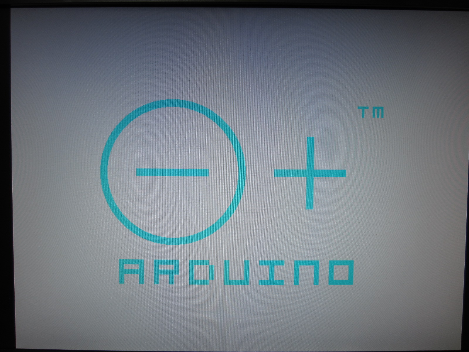
4:3サイズで全面白になった後、しばらく経ってからこんな表示に。
まあ、全く動いてないわけではないので、だいぶ進歩しました^^;