
ESP8266を便利な(笑)MQTTクライアントにするため、smartconfigと組み合わせてみます。センサーの情報をMQTTで一箇所に集めて、表示できるようにするのが目標です。
1.smartconfigの動作確認
まずベースは以前の記事のsmartconfigです。Androidのアプリ側はESP8266 smartconfigで動作することは確認しました。
2.ライブラリのインストール
ArduinoIDEで「ツール→ライブラリを管理」でライブラリマネージャーから「Adafruit MQTT Library」をインストールします。
3.ソースの結合
ソースを結合して以下の通りとしました。難しいところはありません。ついでに、NTPでの時刻合わせ、タイマ割り込みの処理も記述も追加しておきました。
トピックは /feed/sensor/番号 にすることにしました。
できればこの際、SSL化もしたかったのですが、mosquittoのブローカ側のSSL化すらうまく行っていないので今回は見送りです。どちらにせよ、プライベートIPアドレスの中での運用なのであまり気にする必要はないのですが。
※あちこちからの切り貼りです。
#include <ESP8266WiFi.h>
#include <WiFiUdp.h>
#include "Adafruit_MQTT.h"
#include "Adafruit_MQTT_Client.h"
/*****************************************************************************/
/* MQTT Client */
/************************* Adafruit.io Setup *********************************/
#define AIO_SERVER "10.89.105.1"
#define AIO_SERVERPORT 1883 // use 8883 for SSL
#define AIO_USERNAME "username" // 適当に変更(未使用)
#define AIO_KEY "password" // 適当に変更(未使用)
#define SERIALNO "0001"
/************ Global State (you don't need to change this!) ******************/
// Create an ESP8266 WiFiClient class to connect to the MQTT server.
WiFiClient client;
// or... use WiFiFlientSecure for SSL
//WiFiClientSecure client;
// Setup the MQTT client class by passing in the WiFi client and MQTT server and login details.
Adafruit_MQTT_Client mqtt(&client, AIO_SERVER, AIO_SERVERPORT, AIO_USERNAME, AIO_KEY);
/****************************** Feeds ***************************************/
Adafruit_MQTT_Publish motion = Adafruit_MQTT_Publish(&mqtt, "/feeds/sensor/" SERIALNO);
Adafruit_MQTT_Subscribe command = Adafruit_MQTT_Subscribe(&mqtt, "/feeds/command/" SERIALNO);
char macstr[13]; // Station mode MAC address
/*****************************************************************************/
/* NTP Client */
#include <time.h>
#define JST 3600*9
/*****************************************************************************/
/* Timer interrupt */
#define MS2CLK(ms) (ms * 80000L)
uint32_t nxTim;
// 割り込みハンドラ
void timer0_ISR (void) {
nxTim += MS2CLK(100); // 100msec
timer0_write( nxTim );
// 割り込み処理
digitalWrite(13, 1-digitalRead(13)); // Blink the LED
}
/*************************** Sketch Code ************************************/
void setup() {
uint8_t cnt = 0;
// set for STA mode
WiFi.mode(WIFI_STA);
// put your setup code here, to run once:
Serial.begin(115200);
Serial.flush();
Serial.println("\r\n");
// led status at pin4
pinMode(12,OUTPUT);
digitalWrite(12, HIGH); // turn the LED on (HIGH is the voltage level)
// led status at pin5
pinMode(13,OUTPUT);
digitalWrite(13, HIGH); // turn the LED on (HIGH is the voltage level)
//configure pin0
pinMode(0, INPUT_PULLUP);
// deplay for 2 sec for smartConfig
Serial.println("2 sec before clear SmartConfig");
delay(2000);
// read pullup
bool isSmartConfig = digitalRead(0);
if (isSmartConfig == false) {
// bink for clear config
blinkClearConfig();
Serial.println("clear config");
// reset default config
WiFi.disconnect();
}
// if wifi cannot connect start smartconfig
while(WiFi.status() != WL_CONNECTED) {
delay(500);
Serial.print(".");
if(cnt++ >= 15){
WiFi.beginSmartConfig();
while(1){
delay(500);
if(WiFi.smartConfigDone()){
Serial.println("SmartConfig Success");
blinkSmartConfig();
break;
}
}
}
}
Serial.println("");
WiFi.printDiag(Serial);
// Print the IP address
Serial.println(WiFi.localIP());
// タイマ割り込みの設定
noInterrupts();
timer0_isr_init();
timer0_attachInterrupt(timer0_ISR);
nxTim = ESP.getCycleCount() + MS2CLK(100); // 100msec
timer0_write( nxTim );
interrupts();
// time set with NTP
configTime( JST, 0, "ntp.nict.jp", "ntp.jst.mfeed.ad.jp");
// Setup MQTT subscription for command feed.
mqtt.subscribe(&command);
//
uint8_t mac0[6];
WiFi.macAddress(mac0);
sprintf(macstr,"%02X%02X%02X%02X%02X%02X", mac0[0], mac0[1], mac0[2], mac0[3], mac0[4], mac0[5]);
}
void blinkSmartConfig() {
digitalWrite(13, HIGH); // turn the LED on (HIGH is the voltage level)
delay(50); // wait for a second
digitalWrite(13, LOW); // turn the LED off by making the voltage LOW
delay(50);
}
void blinkClearConfig() {
int i=0;
while(i<=3) { digitalWrite(13, HIGH); // turn the LED on (HIGH is the voltage level) delay(100); // wait for a second digitalWrite(13, LOW); // turn the LED off by making the voltage LOW delay(100); i++; } } uint32_t x=0; void loop() { time_t t; struct tm *tm; char msg[64]=""; bool isSW1 = digitalRead(0); if(isSW1 == false){ for(int i=5;i>0;i--){
delay(1000);
Serial.println(i);
}
Serial.println("Power off");
delay(500);
pinMode(15,OUTPUT);
digitalWrite(15, HIGH); // Power-off the board (HIGH is the voltage level)
delay(5000);
}
digitalWrite(12, 1-digitalRead(12)); // Blink the LED
/*******/
/* NTP */
t = time(NULL);
tm = localtime(&t);
sprintf(msg,"%s %s %04d/%02d/%02d %02d:%02d:%02d %ld %d",
SERIALNO,macstr,
tm->tm_year+1900, tm->tm_mon+1, tm->tm_mday,
tm->tm_hour, tm->tm_min, tm->tm_sec,
(long)t,x++);
/********/
/* MQTT */
// Ensure the connection to the MQTT server is alive (this will make the first
// connection and automatically reconnect when disconnected). See the MQTT_connect
// function definition further below.
MQTT_connect();
// this is our 'wait for incoming subscription packets' busy subloop
// try to spend your time here
Adafruit_MQTT_Subscribe *subscription;
while ((subscription = mqtt.readSubscription(1000))) {
if (subscription == &command) {
Serial.print(F("Got: "));
Serial.println((char *)command.lastread);
}
}
// Now we can publish stuff!
Serial.print(F("\nSending message : "));
Serial.print(msg);
Serial.print("...");
if (! motion.publish(msg)) {
Serial.println(F("Failed"));
} else {
Serial.println(F("OK!"));
}
// ping the server to keep the mqtt connection alive
// NOT required if you are publishing once every KEEPALIVE seconds
/*
if(! mqtt.ping()) {
mqtt.disconnect();
}
*/
}
// Function to connect and reconnect as necessary to the MQTT server.
// Should be called in the loop function and it will take care if connecting.
void MQTT_connect() {
int8_t ret;
// Stop if already connected.
if (mqtt.connected()) {
return;
}
Serial.print("Connecting to MQTT... ");
uint8_t retries = 3;
while ((ret = mqtt.connect()) != 0) { // connect will return 0 for connected
Serial.println(mqtt.connectErrorString(ret));
Serial.println("Retrying MQTT connection in 5 seconds...");
mqtt.disconnect();
delay(5000); // wait 5 seconds
retries--;
if (retries == 0) {
// basically die and wait for WDT to reset me
while (1);
}
}
Serial.println("MQTT Connected!");
}
ついでに、基板の回路図も再掲載です。
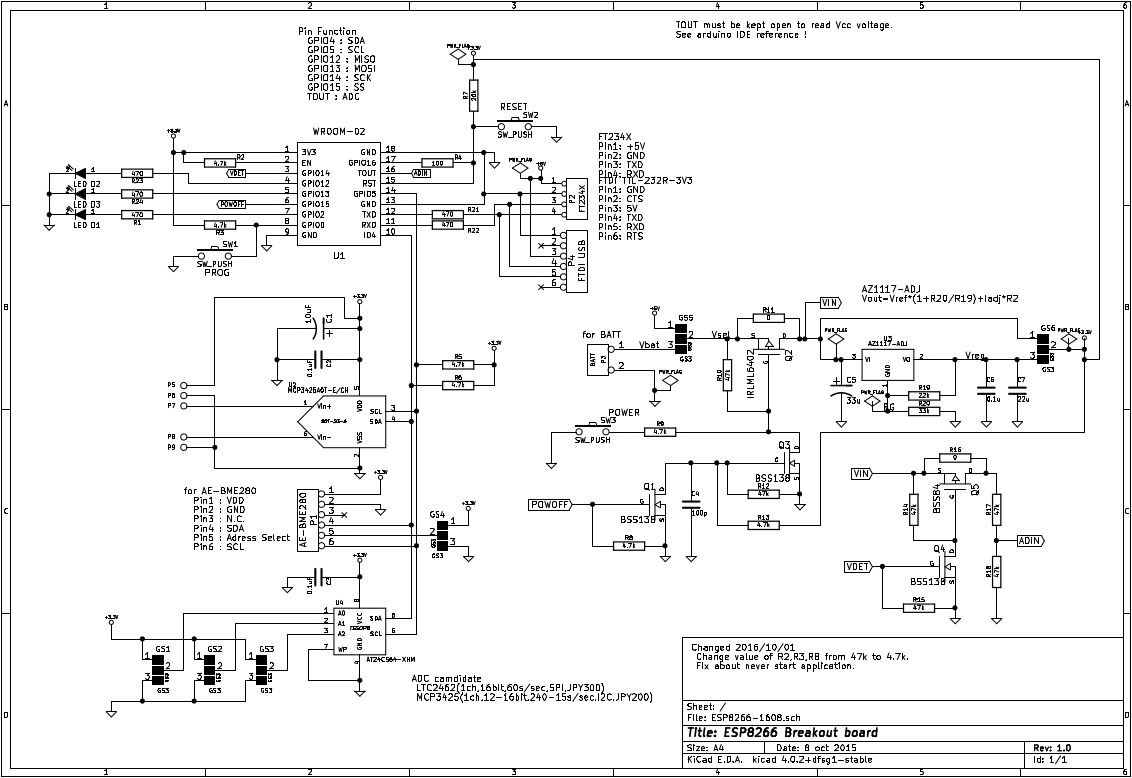
実装部品
ミニマム実装:
 半田面
    GS5 2-3
    GS6 2-3
    C6  0.1u
    C7  22u
    R1  470
    R2  4.7k
    R3  4.7k
    R4  100
    R7  20k
    R8  4.7k
    R11 0Ω
    R19 22k
    R20 33k
    R21 470
    R22 470
    R23 470
    R24 470
 部品面
    U3  AZ1117-ADJ
    D1  LED
    D2  LED
    D3  LED
    SW1 タクトSW
    SW2 タクトSW
    C5  33u